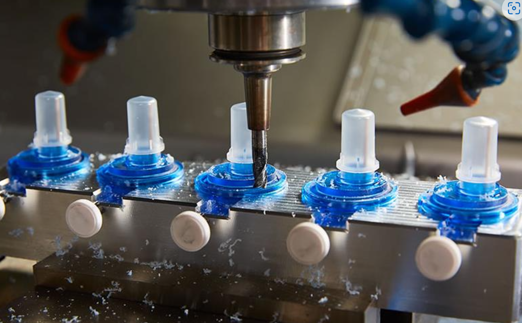
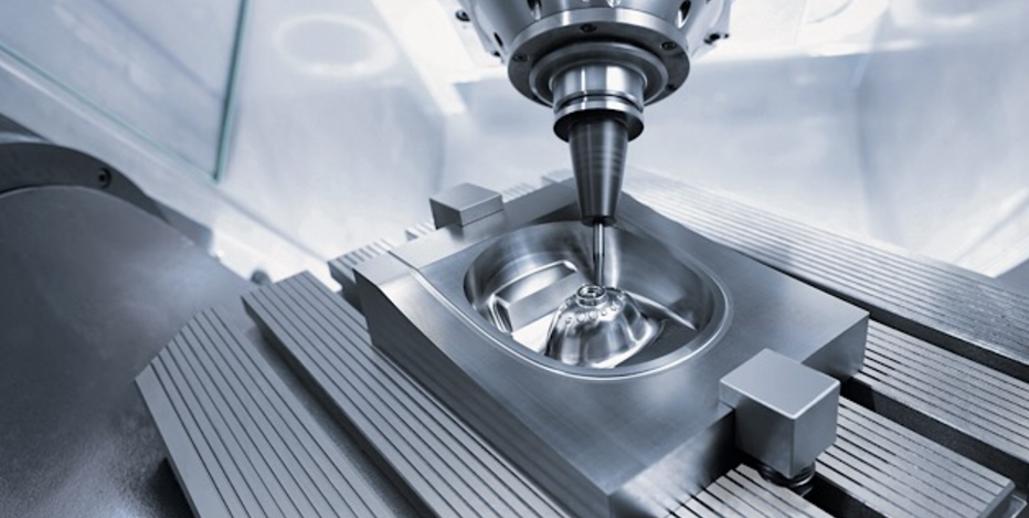
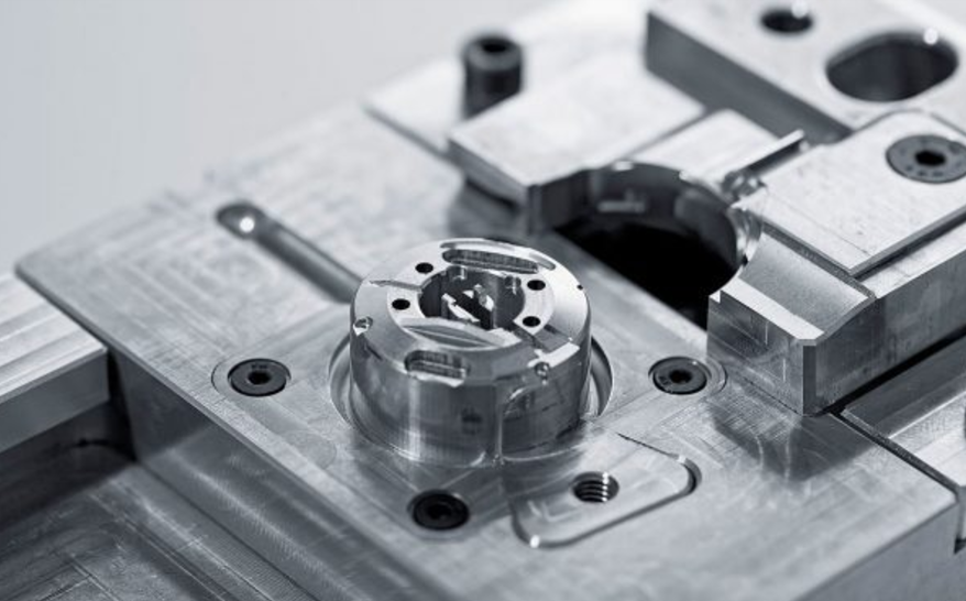
Manufacturing models and era parts fast and cost-efficiently is routinely an altering act of prototype machining capabilities. There’s too an optimized parcel arranged for those capabilities in prototype machining. As such, there is an unassuming bunch of imperative considerations when arranging parts for handling and turning shapes that can enliven era time while reducing costs. Consider crevice profundities, threading, divider thickness, and other machining capabilities to diminish era time and fetched for any protype machining project.
Table of Contents
TogglePrototype Machining Hole Truth:
Anyone who has gone through more than 5 minutes in a shop knows what a boring bit looks like and what it does. For the preeminent parcel, be that because it may, crevices are interpolated with an end mill rather than entered. This machining procedure gives magnificent flexibility in terms of the hole sizes available with a given instrument and offers prevalent surface wrap up than that reachable with a bore. It besides grants us to utilize the same instrument for machining spaces and pockets, reducing cycle time, and parcel took a toll. The because it was disadvantage is that crevices much more than six separations over significant finished up a challenge due to an endmill’s obliged length and may require machining from both sides of the parcel.
Tall Walls And Tiny Features Of Prototype Machining:
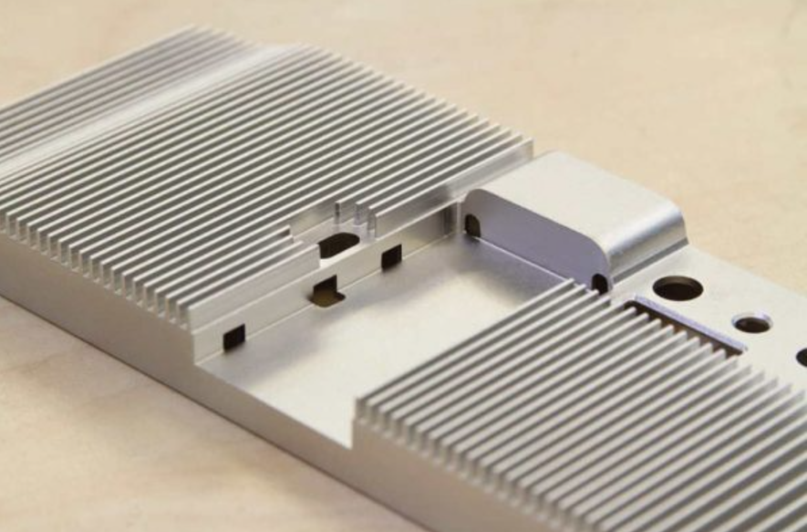
All of the prototype machining toolsets are comprised of carbide cutting gadgets. This super rigid texture offers the foremost extraordinary instrument life and proficiency with negligible avoidance. Be that as it may without a doubt the foremost grounded devices dodge, as do the metals and especially plastics being machined. Since of this, divider statures and highlight sizes are especially subordinate to the individual parcel geometry as well as the toolset being utilized. For the event, the least include thickness is 0.020 in. (0.5mm) and the foremost extraordinary incorporate significance is 2 in. (51mm), but that doesn’t brutal you’ll be able to arrange a ribbed heatsink utilizing those estimations.
Threading Right And Prototype Machining:
Boring and thread-making go hand in hand. Various shops utilize “taps” to cut interior strings. Taps see like a screw with teeth and are “threaded” into an as of now entered crevice. We take a more cutting edge approach to string making, utilizing an instrument called a string to prepare to embed the string profile. This makes a correct string, and a single preparing device can be utilized to cut any string degree that gives that pitch (the number of strings per inch), saving era, and setup time. Since of this, UNC and UNF strings from number 2 up to 1/2 in., and metric strings from M2 to M12 are conceivable, all interior a single toolset.
3-Axis 5-axis Of Prototype Machining:
Two specific “flavors” of handling exist at a few stages. With 3-axis machining, the workpiece is held from the foot of the unrefined texture clear while all of the parcel highlights are cut from up to 6 orthogonal sides. With parts greater than 10 in. by 7 in. (254mm by 178mm), because it was the leading and foot can be machined: no side setups! With 5-axis recorded handling, in any case, machining from any number of non-orthogonal sides is conceivable. The toolsets utilized in either case are unclear. What’s unmistakable is the unrefined texture. As with our machines, the circular stock is utilized for 5-axis prepared parts, which presents many inquisitively logical talks around the gauge, geometry, and arranging of the parcel interior that rough texture volume (it’s that whole Pythagorean speculation thing you learned in tall school).

